
One of the most impactful modifications that you can do on your SL1200.
Currently under heavy reviewing
General Idea
The project started as part of an idea by Jim/6L6 from the diyaudio forum. It was inspired by the previous work of Wayne Colburn of Pass Labs.
While simple, the idea had a profound impact on the performance of the turntable. And it spawned interest that lasts for more than a decade.
The entire original modification had three parts. Moving the transformer and the rectification into an external case away from the turntable, adding a CRCRC filter, and replacing the transistor-based regulator.
In this project we will cover the first part.
STOP! – Safety First
This project deals with mains electricity
Projects like this typically involve deadly high voltages. They must be treated with commensurate respect, and be implemented only by qualified people that can execute them in a safe manner and in accordance to local laws
Initial Implementation
Arguably this part seems to have the biggest effect. It moves any vibration, AC noise, and stray fields from the transformer, away from the turntable and its high-gain phono stage inputs.
This requires you to remove the transformer from its cavity in the chassis, and then desolder the rectifying bridge D1 and its filtering capacitors C5 and C6 from the turntable’s PCB.
TODO: Check notes about other peripheral pcbs?
Most of the time it is suggested to keep the stock transformer. It has the right rating, it is soft mounted to reduce any vibration, and is properly shielded. Some people have opted to replace it with a toroid for less vibration. It has also been suggested to choose one with a lower Voltage, so that the regulator does not have to drop so much of it as heat. TODO: Verify numbers. The rectified and filtered secondary gives ~40V DC and the regulator has to drop this to ~21V. While spinning, the turntable pulls ~250mA. Which means the regulator has to dissipate almost 5W in heat.
STOP! – Safety First
Before you put yourself or others in danger, think very carefully about whether you are qualified to carry out this work in a safe manner and in accordance to local laws and regulations
Safety is your own responsibility
Please read our Disclaimer for more information
The transformer is then installed in an external enclosure.
I will avoid giving specific instructions on how to do this since this project is not meant for inexperienced people, and different areas require different things from mains connected equipment.
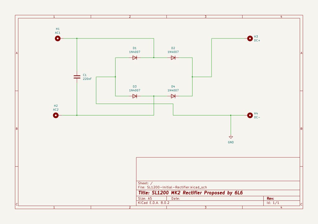
Other than that, we also need to transfer the rectifier to the same enclosure. The initial idea specified 1N4007 diodes. The 220nF filtering film capacitor is also kept. The rectifier circuit is simple enough and can be soldered point to point on some type of terminal strip. Although I suggest that you also do the second step at the same time, and get a PCB for both the rectifier and the CRCRC filter.
You also need some kind of umbilical cable to transfer the DC back to the turntable. Some plain cable with a DIN or a traditional barrel connector is perfect for this job.
On the turntable’s side, the DC is fed into the outer holes of the D1 bridge footprint. V+ goes to the left, and V- goes to the right.
TODO: Photo of the pcb
Improved Implementation
The modification is simple and no separate PCB is really required. If you still want one, again, I suggest that you also do the second step and get a PCB for both the rectifier and the filter.
Adding a Quasimodo Snubber
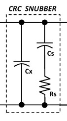
The 220nF film capacitor is not really a snubber. More like just a filter. That said, Mark Johnson from diyaudio forum has written a very nice article about snubbers and has created a jig that can help us calculate a proper one.
Using the cheapomodo version of the jig, I measured the Technics stock transformer and got the following suggested values for the schematic
Cx: 10nF
Cs: 150nF
Rs: 270R
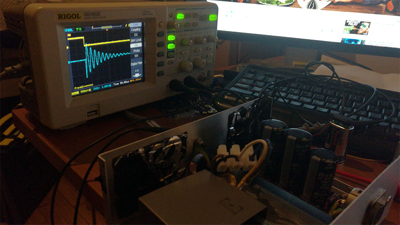
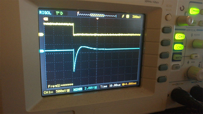
Below you can see the jig ringing the transformer and the diodes, and then taming things with the proper snubbing resistor value.
The snubber schematic basically replaces the 220nF capacitor, and it’s very easy to solder right on top of the rectifier, even point to point.
The measurements were done with the transformer wired for 230V mains. I have no 110V to measure, but if the same transformer is used, then something like a 250R for Rs should be a good enough value for a first evaluation.
Support for bigger and dual diodes
While the 1N4007 works like a charm, there might be a benefit in using bigger diodes in something like a TO22O or even a dual TO247-3 package. This gives us better heat dissipation and support for higher currents (both working and inrush).
Final Schematic
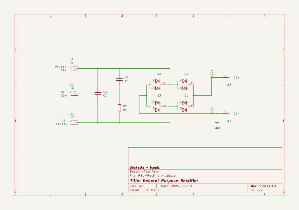
The only thing left to explain is the AC pads to the left. They are supposed to help the builder solder in different transformers, without having any cables flapping in the breeze in the new chassis. Either with secondaries in parallel (P1 in parallel to P2) or in series (S1 in series to S2).
Final PCB
The rectifier project is not available as a separate PCB. If you are interested in getting one, please check the second part that includes the filter on the same PCB.
Suggested Parts:
Rectification diode: 1N4007
Terminal strip: Keystone 534-819
DC Plug: Switchcraft S760K
DC Socket: Switchcraft 722A
References:
Simple, no-math transformer snubber using Quasimodo test-jig
Discussions:
diyaudio – Technics SL-1200 DC Power Supply
Acknowledgments:
Jim – 6L6 from DiyAudio for the initial external PSU idea
Mark Johnson from DiyAudio for his nice Snubber article and calculation jig