How to make a good turntable even better by improving its PSU with a proper CRCRC filter.
Under Heavy Reviewing
Last Updated: 2024-05-29
The idea started about a decade ago in a thread by Jim/6L6 in the awesome diyaudio forum. It was inspired by the previous work of Wayne Colburn of Pass Labs.
While simple, the idea had a profound impact on the performance of the turntable. And it spawned interest that lasts for more than a decade.
General Idea
The modification has three parts that can be executed in series so that you can test and verify your changes.
This project covers the second part, and assumes that you already have a working external PSU according to the actions required by the first step.
STOP! – Safety First
Before you put yourself or others in danger, think very carefully about whether you are qualified to carry out this work in a safe manner and in accordance to local laws and regulations
Safety is your own responsibility
Please read our Disclaimer for more information
Adding a CRCRC filter
This is just a simple CRCRC filter meant to reduce the rectification ripple and noise on the DC output. The proposed values were 4700uF at 63V for the 3 capacitors and 10R at 3W for the 2 resistors. An additional 100nF polypropylene bypass capacitor and a 4.7K bleeder resistor were also specified. The values are just indicative. The filter will work nicely with a wide range of parts.
Below is the original schematic proposed by Jim/6L6
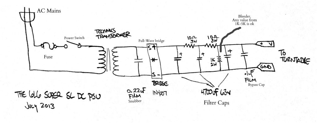
The whole PSU is easy to solder point to point, although a nice PCB will make this tidier and easier.
Improved Implementation
Smaller Resistor Values
After using similar filters in various projects, I have noticed that the 10R resistors act like a virtual brick wall for the current, starving the following capacitors and electronics when a transient occurs. This is usually evident as dips in the voltage that can present themselves as Led flickering.
The dips themselves are not directly a problem. The transformer gives out a high enough voltage to cover for the drop. And the turntable seems to function without issues. The dips appear only as a flickering in the strobe leds when starting or stopping the turntable which boosts the required current from ~250mA to ~550mA.
There is some merit in using those large 10R resistors. They work nicely to demolish the rectification ripple before it reaches the regulator. And the voltage drop benefits the following regulator by removing some of the voltage that they have to dissipate as heat.
On the other hand, the regulator should already be good enough at removing the low frequency ripple. And lower values might allow for better transient response. Especially in marginal cases where the issue might not be evident as led flickering.
TODO: Need to do some further experimentation to pinpoint best values. Until then, the proposed values work nicely and have a very big positive impact on the turntable.
Move the last RC stage close to the load
The original filter specifies 3 large RC stages and a 100nF at their output, all soldered close together and inside the external PSU case. While this sounds nice, it does not really take into consideration the effect of the umbilical cable. By moving the last RC stage and the 100nF capacitor close to the turntable’s PCB, we are removing any effect caused by the cable’s inductance, and we are providing a large local power bank to help with transients. And the 100nF deals with all accumulated high frequency noise where it matters most.
Please note that the SL1200MK2 pcb already has an input capacitor. The following regulator (at least the one specified in step three) should not have an issue dealing with the added capacitance and reduced ESR. But in case you are experimenting, please make sure to remember those additional input capacitors C1 and C3.
Additional helper parts
We are basically building a rectifier plus CRC filter circuit. Which quite honestly is a very useful general purpose circuit. So we might as well allow for some extras that would make the circuit easier to use with a wider range of different projects. Like allow for additional parallel resistors to avoid overpaying for high wattage ones. Or a led indicator and a bleeder resistor. Or allow for footprints for a wider range of capacitors. And add a few extra output pads for possible additional boards added later.
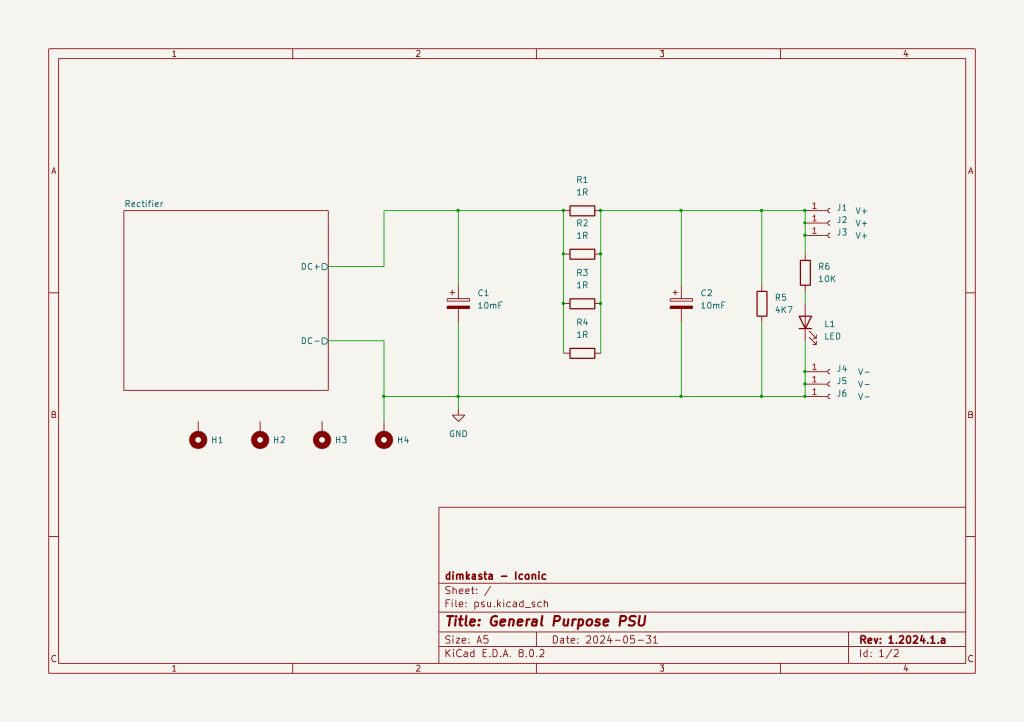
Final Schematics
This final schematic assumes that we have moved the final RC stage into the turntable, so we are seeing only a CRC filter.
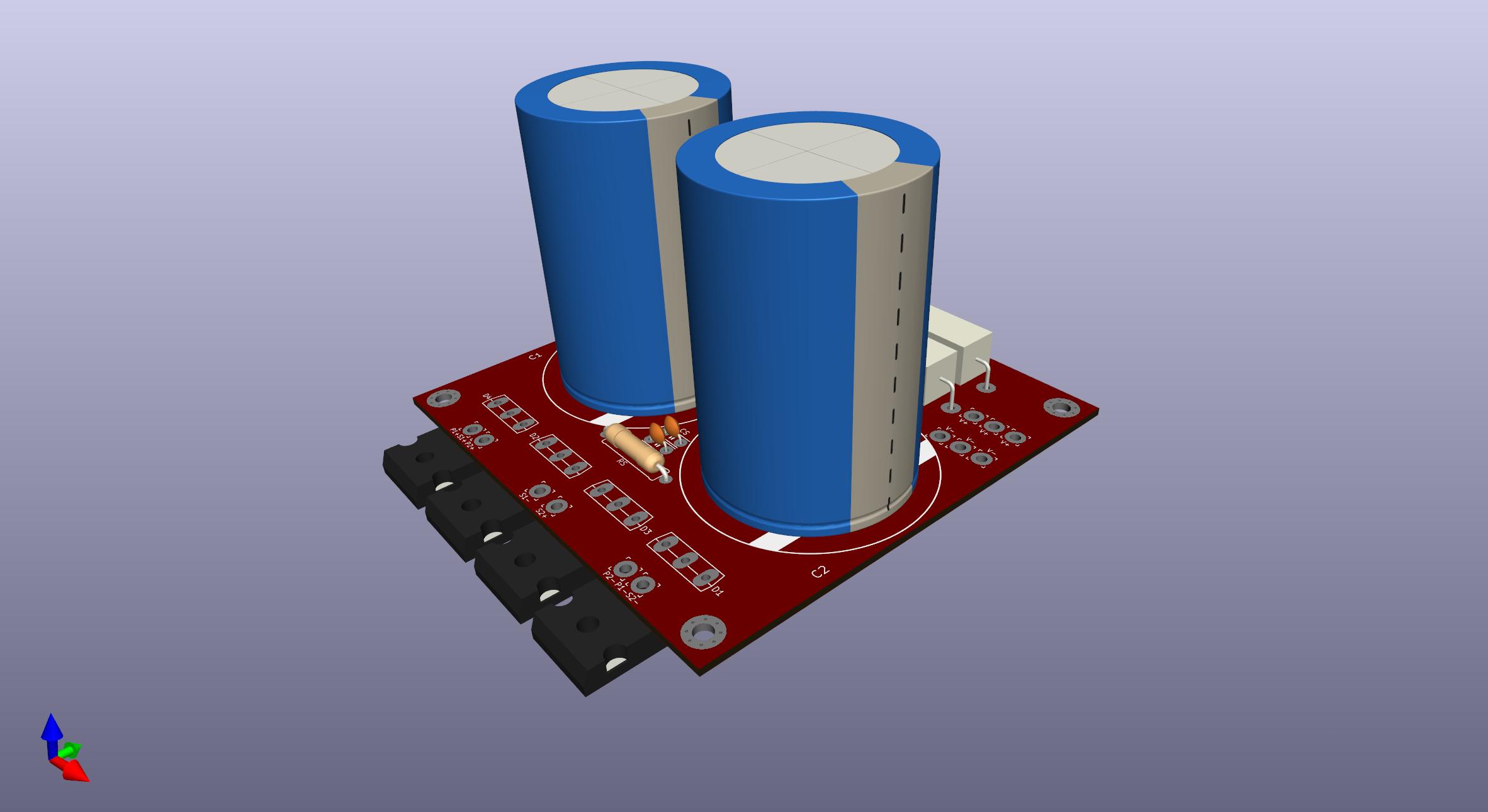
Final PCB
The PCB is currently under evaluation
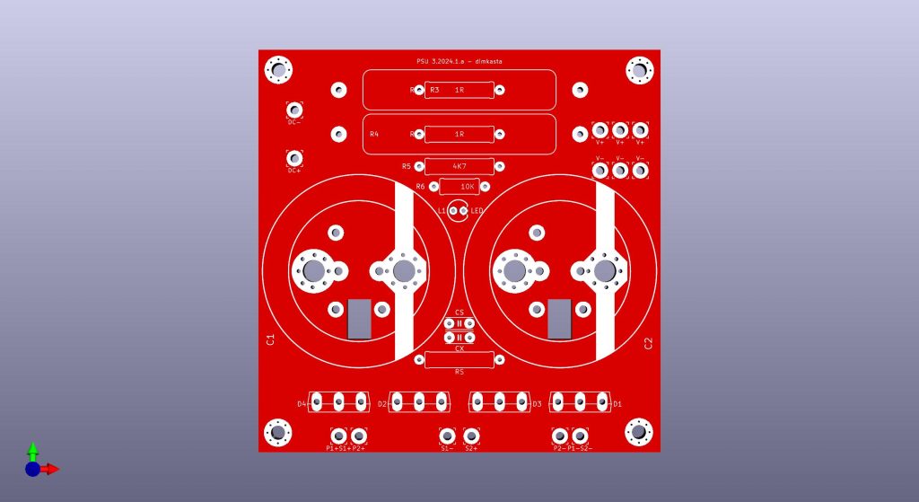
It can be populated with either high or lower wattage parts. And supports a wide range of capacitors with 10mm lead spacing, 5-pin ones, or even big screw-mount ones like PEH169 or sikorels.
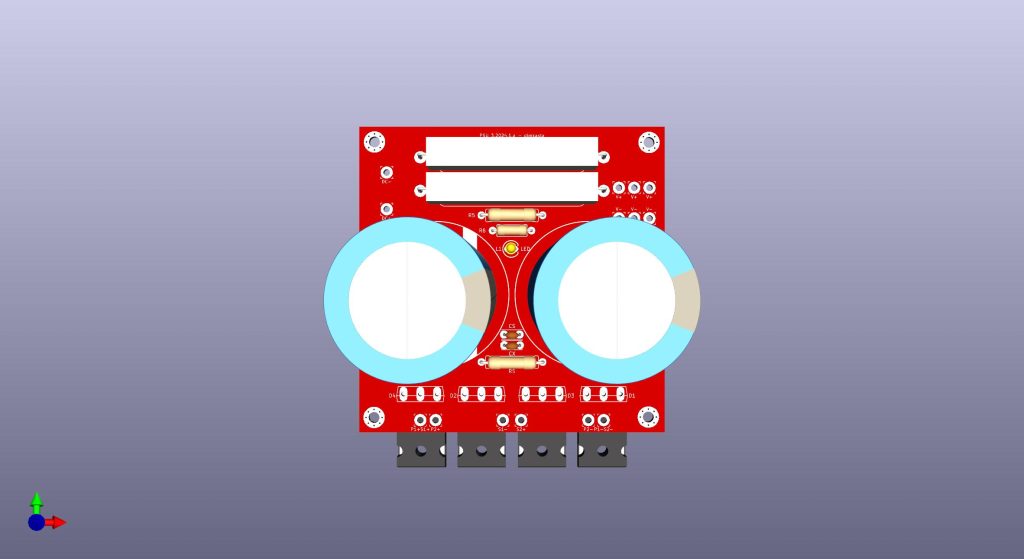
It can also be implemented with lower wattage packages, or even plain 1/4W parts. The middle pin of the T247-3 package is the cathode.
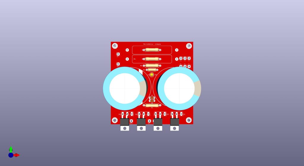
In case you want to bypass the rectifier and use it as a plain CRC filter, you can use the DC wirepads on the left.
Discussions
The art of sound – SL-1200-DC-Power-Supply-DIY
diyaudio – Technics SL-1200 DC Power Supply
Acknowledgements
Jim/6L6 for the initial Idea
Wayne Colburn of Pass Labs for his initial work on Technics turntables