I made a few changes to the schematic and PCB.
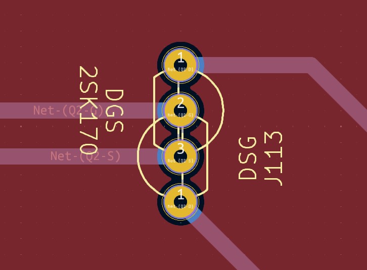
The biggest one was to create a jfet footprint that supports both DGS and DSG packages. The idea came from the PCBs designed by Passworks for the 2022 DIY front-end, published at diyaudio. Basically, it allows a plain 3-pin symbol for the schematics, and defines a 4-pin footprint with the two outer pins both being the drain. Which allows the builder to populate whatever side makes sense for their BOM.
Here is a closeup of how this looks in a pcb
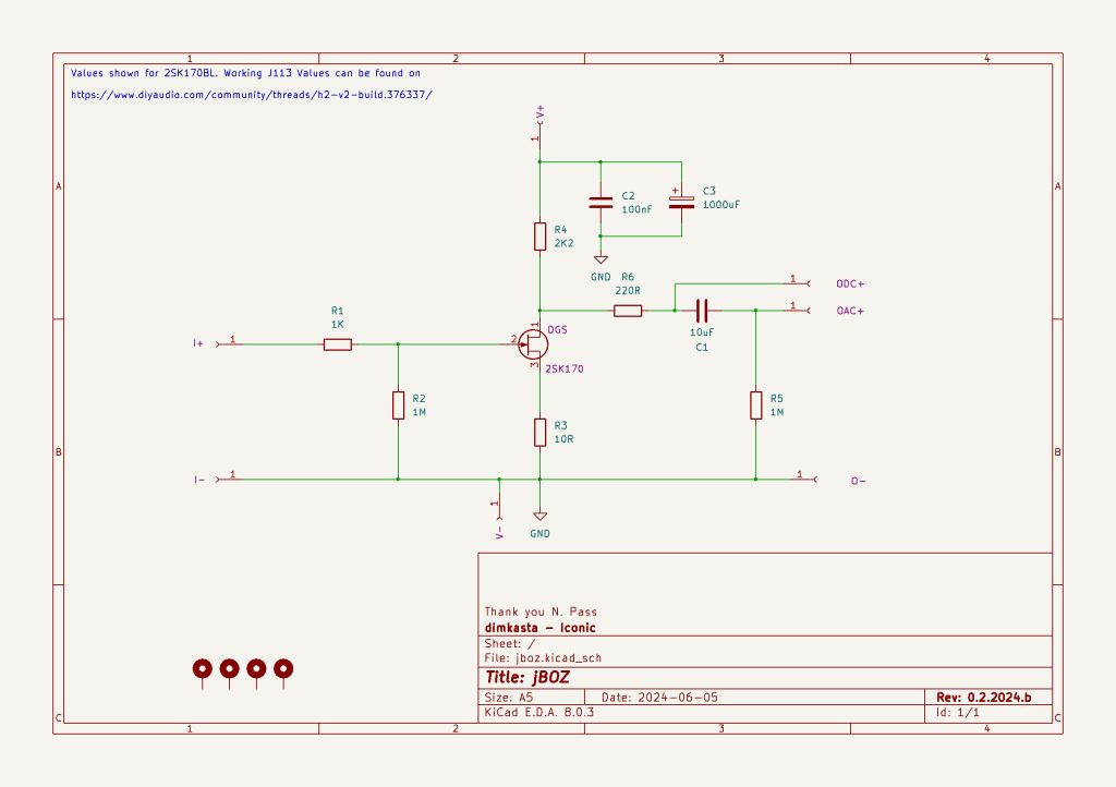
Below you can see the current version of the schematic. I am doing some final checks before ordering samples.
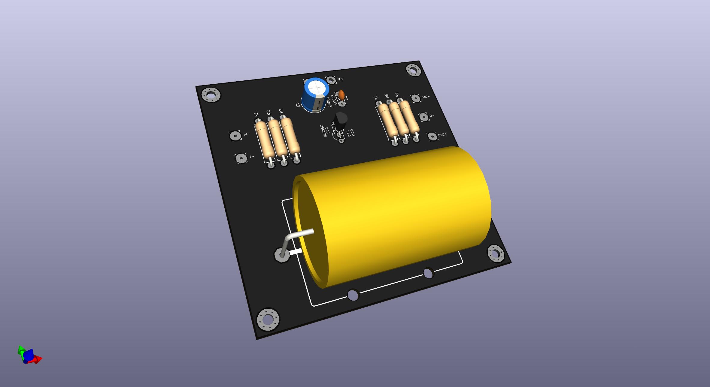
And here is what the current PCB looks like
