Catching up with my numerous projects, it’s time that I revisited my version of what became popular in diyaudio and pass labs circles as the jBoZ preamp.
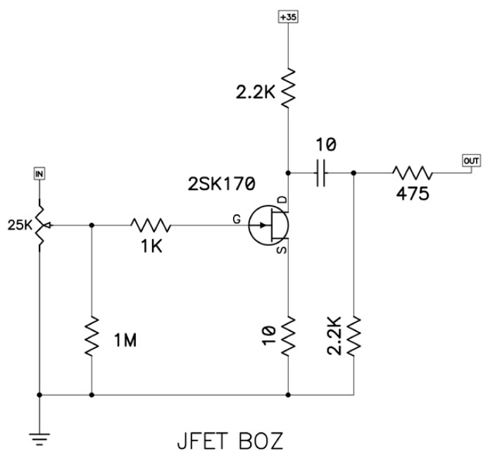
There is nothing particularly critical about the circuit. It’s pretty much a simple jfet circuit, very close to what one can find in electronics tutorials. Below you can see the original schematic, posted by Nelson Pass in Diyaudio back in 2007.

As a simple common source circuit, it has voltage gain, and has an AC coupled output with reversed polarity. It also specifies the sought after but discontinued 2SK170.
A couple of changes I am considering so far:
The first is to move the output resistor before the output capacitor. That way, I can still get its protection even when using the circuit with a next stage that is known to be AC coupled, allowing me to leave out the output capacitor (10uF) and its bleed resistor (2.2K).
The second change, is to add a second TO-92 footprint to allow for alternative jfets. The 2SK170 uses a DGS package. So I am also adding a DSG footprint for parts like J113.
I am also switching the output resistor from 475 to 220 ohms. Mostly because I already have a lot of them, and because it would reduce the output impedance a bit. I am also switching the output capacitor bleeder to 1M. The 2.2K specified sounds like it would interact too much with the input impedance of the following stage.
I am adding a couple of 1000uF capacitors to act like a local bypass.
And finally I am adding two outputs, one AC coupled like specified in the schematic, and one DC coupled, taking the output right before the capacitor.
In general, I am not too crazy about using this circuit as a preamp in my audio system. Its increased second harmonic does not appeal to me very much. But it will be a very nice match for my simple guitar amplifier project. Along with a few changes inspired by robrobinette.com it will be perfect.
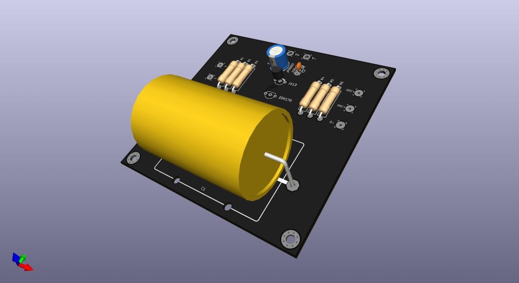
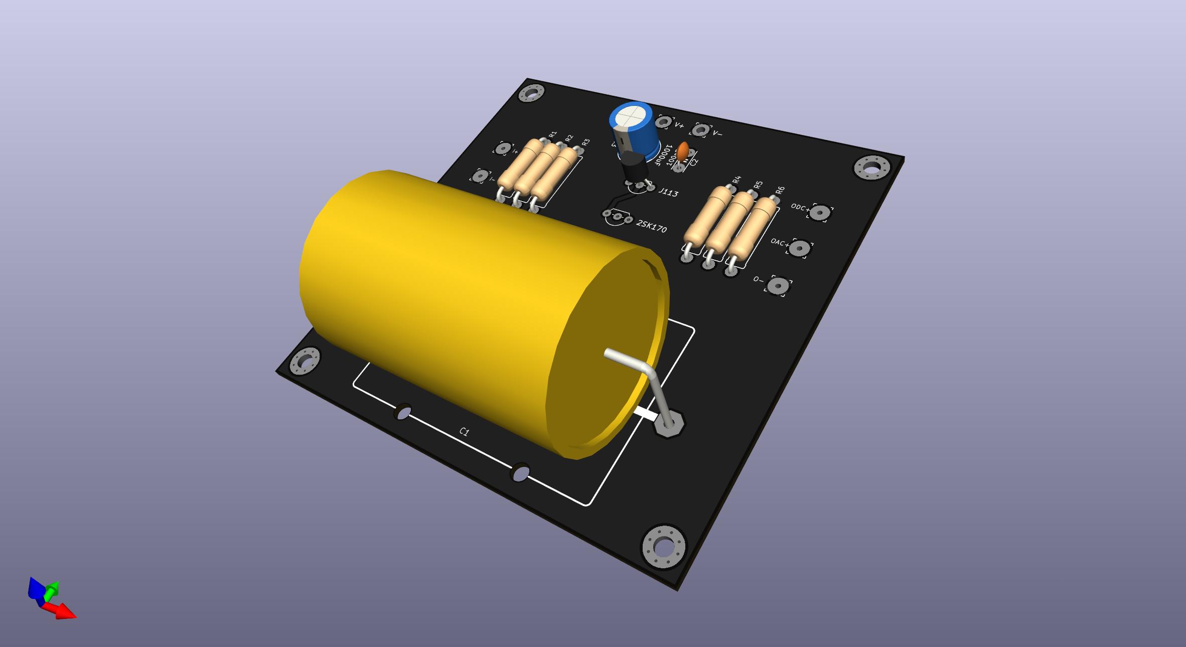
And here is a 3d rendering of what I have so far. I expect to finalize the schematic soon and order a first test batch.

