I recently started modifying my second SL1200. It was a nice opportunity to practice my Kicad and update my old PCBs, since Autodesk decided to kill Eagle.
I have to say that Kicad has come a long way since I last tried it, back in version 5. It is super easy to import eagle projects, even with custom library parts, and import everything in your own libraries.
So I have recreated the schematics and the PCBs from my old entry regulator Eagle projects. It was also a nice opportunity to try the hierarchical schematics. I have created the LM317 schematic as a separate sheet
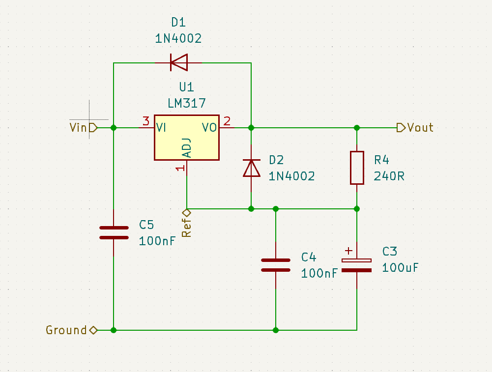
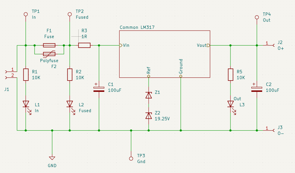
And added the specific implementation parts in the root project
Hopefully, this allows reusing the schematic in case I want to add extra separate regulators for either the control or the FG amplifier.
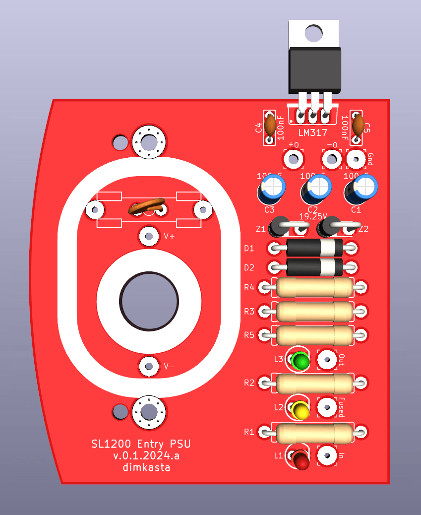
In comparison to the original design by 6L6, this one includes a few helper parts like a fuse/pptc, test points and separate led indicators for each stage of the regulator. I have also added two 100nF capacitors. One before the LM317 since it’s highly recommended in the datasheet if the capacitor bank is away from the chip. And the second next to the zener diode to reduce its noise even further.
The PCB is an evolution of my old design that fits on top of the bottom entry hole of the SL1200 chassis. It has an 8mm hole to fit a barrel jack to plug the DC umbilical coming from the external unit.
The pads use my usual custom footprints with oversized pads. Which makes PCBs easier to solder and test, while allowing for any bigger resistor type like RN70 or carbon composition.
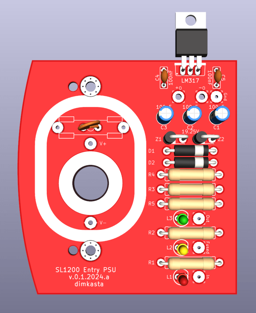
I still need to review my old notes and remember why I made some choices, but overall I am happy with the layout and will order a test batch soon.