I received the new boards a few weeks ago, but did not have the time to work on them.
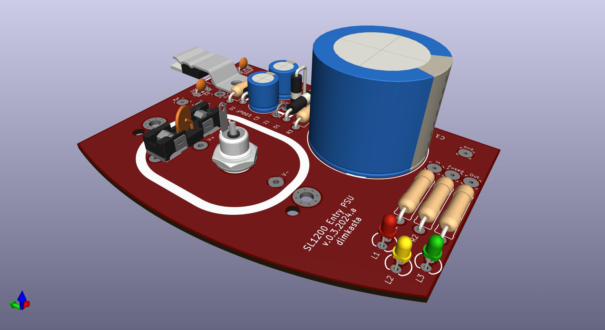
They contain a few new features in comparison to my 2017 boards. The bigger one is the monitoring leds and testing points at the bottom. And then the big 35mm electrolytic and 100nF bypass ceramic capacitors. And finally a hole to attach a clip to push the TO220 chip to the aluminum pad, to avoid having to drill and tap holes.
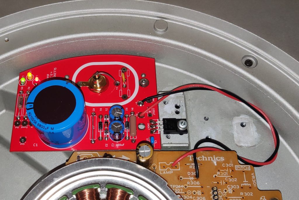
I have finally found some time to install it to my turntable. The attachment point of the output is a bit arbitrary, but keep in mind that the Technics board is single sided and has huge runs of thin and high inductance tracks. Ideally you want the regulator output close to the load, with appropriate local bypass capacitors. This will have to be dealt with on a separate project.
Here are my findings and decisions for the final version
I will remove the 5×20 ceramic fuse and R3 in favor of a PPTC MF-R050 fuse. The PPTC has about 0.8 Ohms of resistance in normal operating conditions, so it adds a bit of filtering. The initial idea by 6L6 specified 10 Ohm resistors, which in my opinion are huge and virtually starve the electronics during large transients. I have tested the PPTC using my bench PSU. I shorted the output and gradually ramped up the current. The small device shuts off pretty fast once the current reaches 1A, which is exactly what we want from our DC fuse.
After some though, I also decided that the hole for the clip is not really that helpful and it takes a lot of valuable space near the LM317. It’s easy to attach the TO220 to the aluminum pad anyway. I will remove it for the final version.
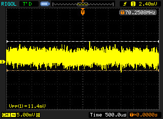
The large electrolytic and its ceramic bypass work like a charm.
Measuring the noise, I got around 12mV P2P on my scope with the BW limit enabled. And adding C4 had no visible effect. So I will remove it since I do not fully understand how it interacts with the capacitor suggested by the datasheet.
In the meantime, I am torturing the PSU by running the turntable for the whole day. The Greek summer makes things more challenging, since there is a steady ambient temperature of 32 degrees Celcius. So far the LM317 deals with things like a champ and shows no signs of overheating, which is nice if we consider the huge voltage that it has to drop (~20V).
For the final version, I decided to also add a 22V TVS on the output to protect the rare chips from accidents (I have already accidentally baked a couple by passing 36V to them). And the space saved from removing the clip hole and R3 will help rearrange things a bit better and closer to the LM317. I will also add a 200R/3W preloading resistor so that it’s easier to test the regulator on its own, before attaching it to the turntable, risking the rare chips. This will also increase the idle current a bit, pushing the LM317 into ~250mA during spinning, which is still close to its peak ripple rejection area.